A systematic approach that supports the reading and interpretation of technical drawings makes it much easier to understand the content and identify critical tolerances, for example for work preparation or metrology. In addition, the specification can be checked for possible ambiguities, errors or missing information. For us, too, reading all the entries has long been a challenging task, so we have developed procedures to make us more efficient.
This systematic approach is presented in extracts below. For more complex and less clearly visualised components, there is also an alternative proposal, which is described briefly at the end.
Systematic approach
The following steps provide an overview of how we systematically work our way through individual parts in order to include all information:
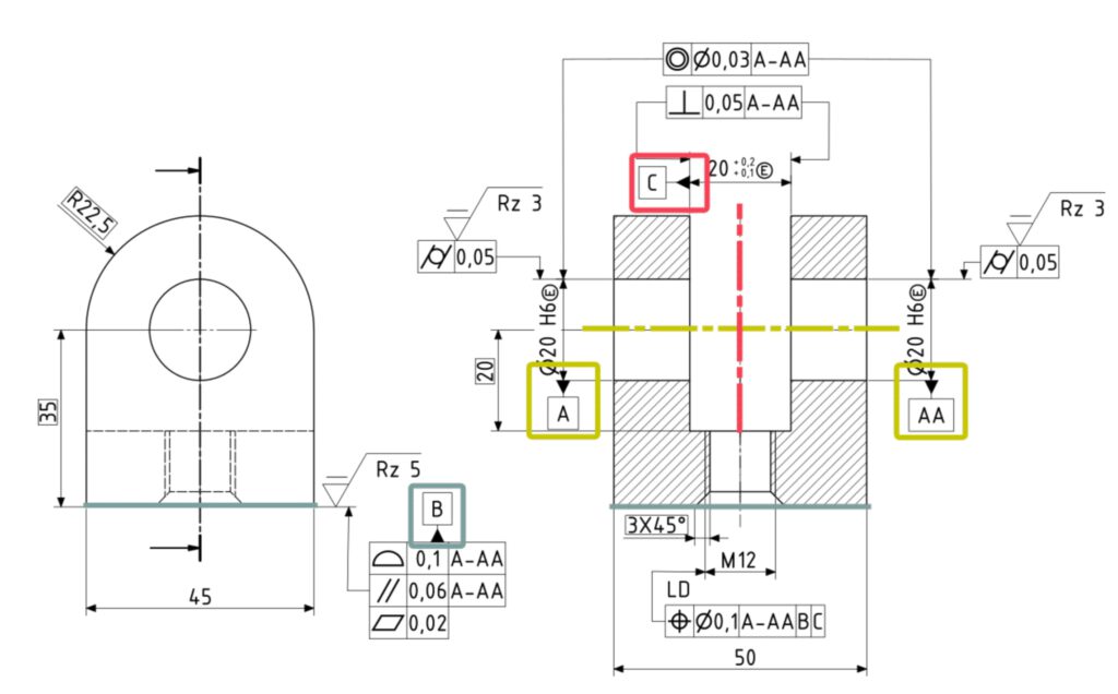
1. read out the title block, in particular to be able to take into account the drawing date for the assignment of standards and general specifications (e.g. general tolerances or general edge specifications).
2. Datum system and identify references, understand the protection of references
3. form, direction, location and running tolerances assess, assign TEDs to the location tolerances
4. size dimensions and changes to the default settings, e.g. with the envelope condition.
5. surface data determine which parameters are entered for which geometry elements
6. further specifications Understand
This approach also forms the basis for the content integrated in our new course on the interpretation of technical drawings. You will also find exercises there.
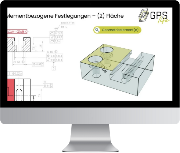
Procedure for more complex components
Alternatively, specifications can also be interpreted in relation to the geometry element. This approach follows the basic idea of the ISO GPS system from ISO 8015 that components are broken down into individual geometric elements. The following image shows a section of what this looks like. The specification for each individual geometry element is thus analysed even more systematically.
This procedure is also presented as "Procedure for reading extensive drawings" in the application module of the above-mentioned course using an example.