With technical progress, components are being manufactured ever more precisely. As a result, simple descriptions with classic plus-minus tolerances are no longer sufficient in many cases, as they are no longer unambiguous in these deviation ranges. Such tolerances are often ambiguous, particularly in the case of step and distance dimensions, because it is not clear exactly what the dimension refers to. For this reason, new tolerance rules were developed many years ago to avoid these ambiguities. At the same time, there are still dimensions for which a plus-minus tolerance is sufficient and sensible.
In order to differentiate between the valid different types of dimensions (so-called size dimensions and theoretically exact dimensions (TEDs)), it is important to understand the basic approach of dividing (partitioning) a component. This involves dividing a component into individual basic geometric elements, for example into surfaces and cylinders. Tolerances are either assigned to individual geometry elements or describe the relationship between several geometry elements.

Cylinders and two parallel flat surfaces often functionally belong to a special group of geometric elements, the so-called linear dimensional elements. These are primarily used to ensure the joinability of components in an assembly. Their definition is specified in ISO 14405-1. The ISO 286 fit system is also geared precisely to this function and helps to clearly recognise linear dimensional elements. In addition, these elements form the basis for the derivation of so-called middle elements, for example centre lines or centre planes.
Dimensions that describe the relationship between geometric elements - i.e. step or distance dimensions - must be specified differently in the ISO GPS system. For an unambiguous description, they are defined with references and geometric tolerances and specified as theoretically exact dimensions (TED). It is important to understand that two parallel, flat surfaces can also be defined both as a size dimension and as a distance dimension. It is precisely this dual role that often makes the distinction difficult in practice.
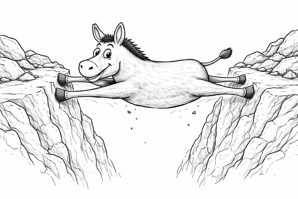
As a simple mnemonic, it is advisable to check whether mean elements can be derived from the surfaces or cylinders under consideration or whether it would make sense to specify a fit. If this is the case, it is usually a linear dimension element. As shown in the following image, the donkey touches both sides at the same time, thus creating a size measure. In the case of cylinders, the assignment is usually unambiguous, although in certain cases they can also be tolerated differently as size dimensions.
Typical dimensions, for example a size dimension (Ø 10 mm) and several distance dimensions as theoretically exact dimensions (18 mm, 25 mm and 45 mm), are entered in the following drawing section. The TEDs determine the location of the geometric elements in conjunction with the references.
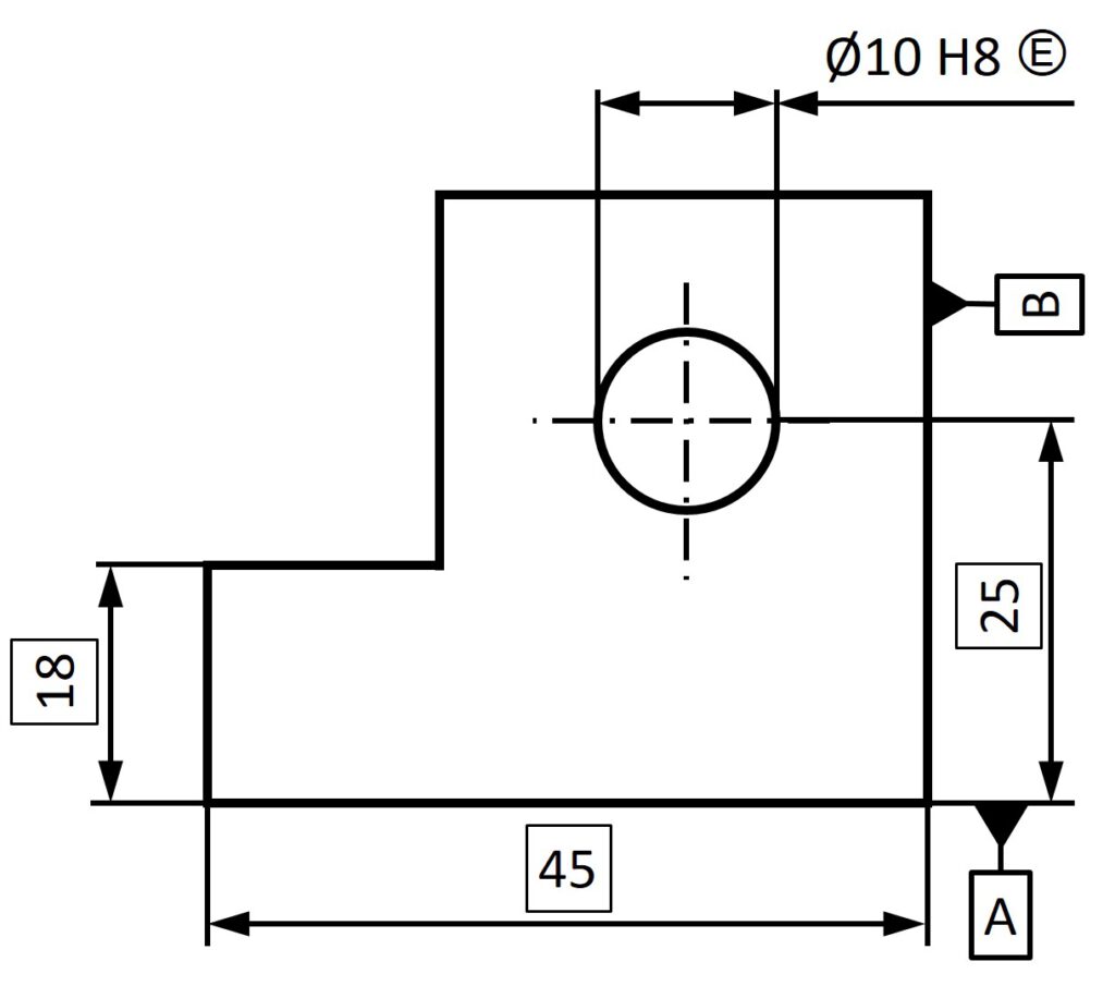
The distinction is significant in the context of the application of ISO 22081. With the knowledge from the previous paragraphs, the entries can be clearly assigned: For step and distance dimensions, the area profile tolerance is used in the reference system (TEDs are often not shown and are taken from the CAD model), while the specification "Linear size" applies to linear size dimension elements. These dimensions are stated directly in the specification.
The detailed explanations of the general tolerances, the systematic differentiation of measurement types and other definitions will be further deepened in the basic courses.